 |
|||
|
|
|||
|
Page Title:
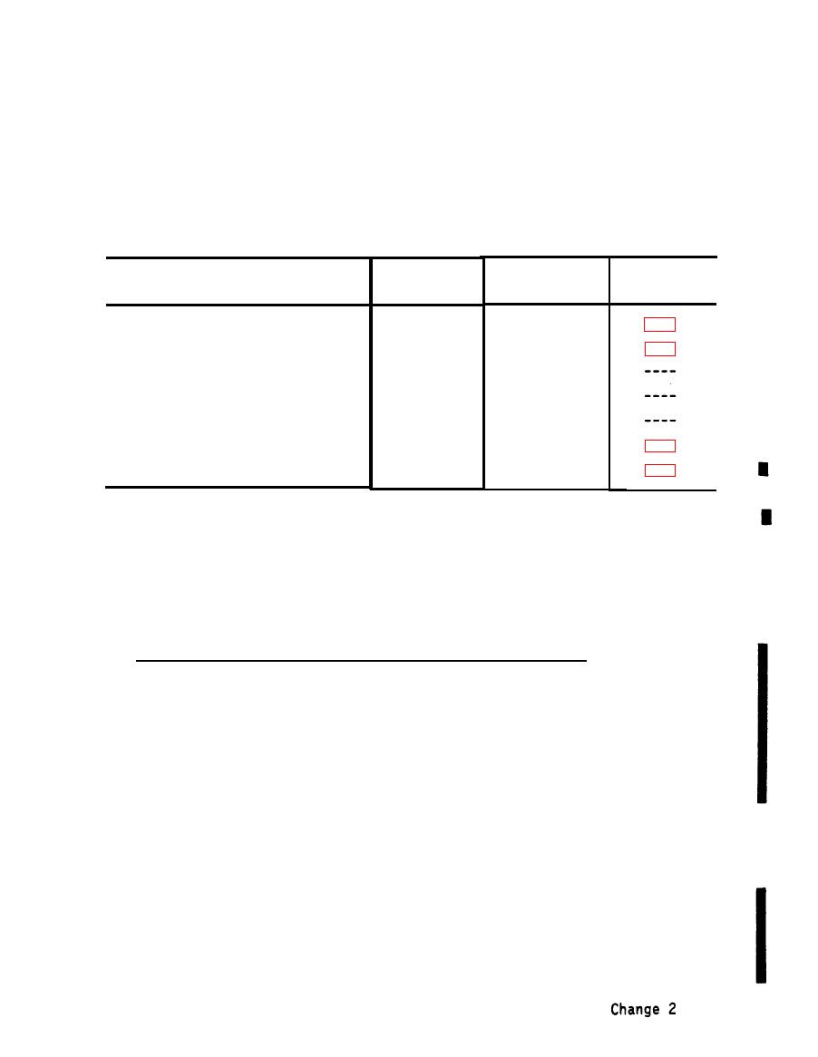
Table 5-3. Receiver Set CCA/Module Identification |
|
||
| ||||||||||
|
|
 TM 32-5865-061-24&P
b. Release the retaining catches located at each side of the circuit card
assembly.
c. Using card extractor tool 5054268, remove the circuit card assembly from
the unit.
Receiver Set CCA/Module Identification
Schematic
Reference
P a r t number
diagram
designation
Component
A5
5051909-1
Buffer Amplifier CCA
5051841-1
A6
Power Supply Monitor CCA
5054967-1
Y1
R e f e r e n c e Oscillator, 5 MHz
5051780-2
A7
E M I Filter Assembly
5052299-2
A8
Indicator Light Assembly
C5075831-1
A10
Filter Assembly
All
C5146983
F i l t e r Assembly (SEE NOTE)
NOTE :
FILTER ASSY A11 INSTALLED ON SERIAL NOS. 143 AND ABOVE
d. To install a replacement, insert the card into the guides in the card
Push down until firmley seated.
holder.
e.
S e c u r e the catches at each side of the CCA.
f. Replace and secure top access cover.
5-4.3 Filter Assemblies (A10) and (A11), Removal/Installation. A10 or A11 is
removed/installed as follows:
a.
R e m o v e A10 or A11 from rear panel as follows:
(1) Supporting the filter assembly, remove and retain the four socket
head screws, washers and lockwashers, securing the filter assembly
to the stand-off posts.
( 2 ) Disconnect A10W1P1 from J24 or A11W1P1 from J27.
b.
Install a replacement as follows:
NOTE
If A10W1P1 or A11W1P1 MASTER key engages properly
skip step (2).
(1) Align the mounting holes in A10 or All chassis with the screw holes in
t h e s t a n d - o f f p o s t s . C h e c k that the master key of A10W1P1 or
A11W1P1 engages properly with A10 or All in this position.
|
|
Privacy Statement - Press Release - Copyright Information. - Contact Us |