 |
|||
|
|
|||
|
|
|||
| ||||||||||
|
|
 TM 11-5820-549-50-1
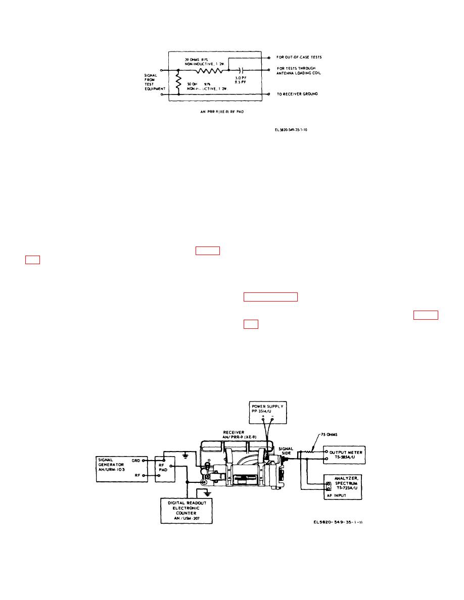
Figure 4-1. Rf pad, construction details.
Section II. TESTS
4-6. AN/PRR-9(XE-9) Sensitivity Test
i. Value obtained in step g shall be at least 10 db
higher than the value obtained in step h.
Remove the antenna from the receiver. Make overall
j. Change the receiver channel frequency to 47
sensitivity test as follows:
MHz (crystal frequency 36.3 MHz) and aline on ID-
a. Place a 51 MHz channel frequency crystal
1189(XE-2)/PR. Repeat steps b. through i.
(crystal frequency 40.3 MHz) in the receiver and aline
k. Change the receiver channel frequency to 57
with ID-1189(XE-2)/PR.
MHz (crystal frequency 46.3 MHz) and aline on ID-
1189(XE-2)/PR. Repeat steps b. through i.
c. Set the PP-3514/U for 3.2 0.1 volts input to the
4-7. AN/PRR-9(XE-9) Squelch Sensitivity Test
receiver.
This test should be run after the sensitivity test in
d. Set the TS-585A/U for 150 ohms.
e. Set the AN/URM-103 for 0.8 microvolts at
normal channel frequency.
channel frequency, and 8 kHz deviation at 1 kHz.
Leave the TS-421A/U off for this test.
f. Adjust the receiver volume control, squelch off,
b. Set the PP-3514/U for 32 0.1 volts input to the
for an audio output power reading of 2.4 milliwatts on
receiver.
the TS-585A/U.
c. Set the TS-585A/U for 150 ohms.
g. Note and record the db indication on the TS-
d. Set the AN/URM-48 for the receiver channel
723A/U in the SET LEVEL position.
frequency and 3.0 kc deviation using 150
h. Change the TS-723A/U from the SET LEVEL
position to the DISTORTION position and note and
record the db indication.
Figure 4-2. AN/PRR-9(XE-9) sensitivity test.
4-2
|
|
Privacy Statement - Press Release - Copyright Information. - Contact Us |