 |
|||
|
|
|||
|
|
|||
| ||||||||||
|
|
 TM 11-5820-549-50-1
d. Adjust T4, T6 and T6, in sequence, for
maximum voltage at TP2. Repeat the adjustments until
no further improvement is obtained.
3-6. Discriminator Alinement
If misalinement is indicated during troubleshooting (para
b. Set the PP-3514/U for 3.2 volts.
ohms
d. Adjust unmodulated frequency of AN/ URM-103
to channel frequency of AN/PRR-9 (XE-9) at 50
microvolts and fine-tune AN/ URM-103 frequency to
produce an indication of 455 kHz 500 Hz on AN/USM-
207.
e. Tune T8 for 0 volts on TS-352B/U.
f. Without changing frequency of AN/URM103, set
modulation at 1 kHz at 8 kHz deviation.
g. Adjust receiver control R7 for 3.5 milliwatt
indication on TS-585A/U.
h. Adjust T7 for minimum distortion indication on
TS-723A/U.
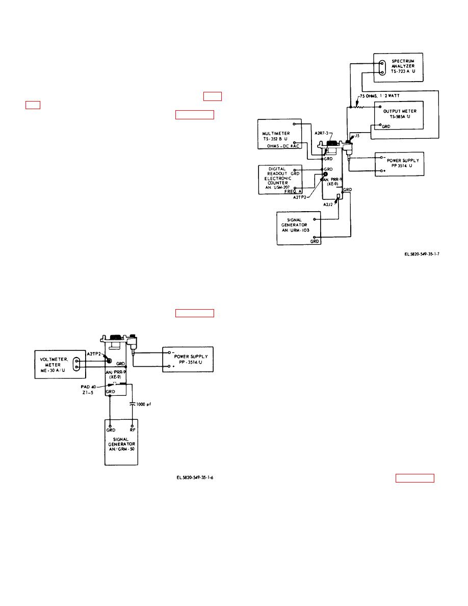
Figure 3-3. AN/PRR-9(XE-9) discriminator
3-7. Local Oscillator Alinement
alinement, test setup.
The local oscillator of the AN/PRR-9(XE-9) is normally
alined on the ID-1189(XE-2)/PR.
An alternate
b. Set the PP-3514/U for 2.6 volts. The lower-
procedure using test equipment is described below.
than-normal voltage will assure satisfactory oscillator
operation under field conditions.
c. Install the desired crystal Y1 in the receiver and
set the receiver for squelched operation.
d. Adjust C15 fully clockwise.
e. Slowly adjust C15 counterclockwise until an
upward indication on the AN/URM-145 meter 100 mv
scale is observed.
Continue to adjust C15
counterclockwise until maximum indication is observed
on the AN/URM-145. The maximum indication should
be about one-quarter turn counterclockwise from the
point of initial upward deflection of the meter. A final
meter reading of 40 to 50 millivolts is typical.
3-8. Squelch Sensitivity Adjustment
The squelch sensitivity is normally adjusted with the ID-
1189(XE-2)/PR.
An alternate procedure using test
equipment is described below.
b. Set the AN/URM-103 to the receiver channel
frequency with 50 microvolt output, and external
Figure 3-2. AN/PRR-9(XE-9) 10.7 MHz i.f. alinement,
modulation.
test setup.
3-3
|
|
Privacy Statement - Press Release - Copyright Information. - Contact Us |
