 |
|||
|
|
|||
|
|
|||
| ||||||||||
|
|
 TM 11-5820-549-50-1
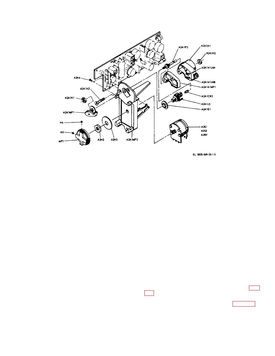
Figure 3-1. AN/PRR-9(XE-9) electronic unit assembly, partially exploded.
Section II. DEPOT ALINEMENT
Item
Technical manual
3-3. Test Equipment and Special Tools Required for
Alinement
Voltmeter, Electronic TM 11-624-14
The following test equipment, special tools and
AN/URM-145
materials are required for depot alinement of Receiving
Materials: Capacitor 1000
Set, Radio AN/PRR-9(XE-9).
pf, 10%,
Item
Technical manual
200 wvdc
Indicator, Channel
TM 11-666-937-12
Resistor, 75
Alignment ID-1189
ohm 5%,
(XE-2)/PRR
1/2 watt
Signal Generator AN/
TM 11-6625-573-15
GRM-50
3-4.
Use of Indicator, Channel Alinement ID-
Signal Generator AN/
TM 11-6625-586-12
1189(XE-2)/PR
URM-108
Multimeter TS-352B/
TM 11-6625-366-16
The channel alinement indicator can be used in making
U
battery tests, or for alinement when the channel
Voltmeter, Meter ME-
TM 11-6620-320-12
frequency of the AN/PRR-9(XE-9) is changed.
30A/U
Digital Readout, Elec-
TM 11-6625-700-10
tronic Counter AN/
3-5. 10.7 MHz i.f. Alinement
USM-207
If misalinement is indicated during troubleshooting (para
Output Meter TS-685
TM 11-5017
A/U
follows:
Analyzer, Spectrum
TM 11-5097
TS-723A/U
b. Set the PP-8514/U for 3.2 volts.
Power Supply PP-
TM 11-6625-617-12
c. At pin 5 of Z1, through a 0.001 uf capacitor,
3514/U
inject an unmodulated 10.7 MHz signal of sufficient
Oscillator, Audio TS-
TM 11-6625-355-12
strength to produce a 15 millivolt ac signal at TP2.
421A/U
3-2
|
|
Privacy Statement - Press Release - Copyright Information. - Contact Us |