 |
|||
|
|
|||
|
Page Title:
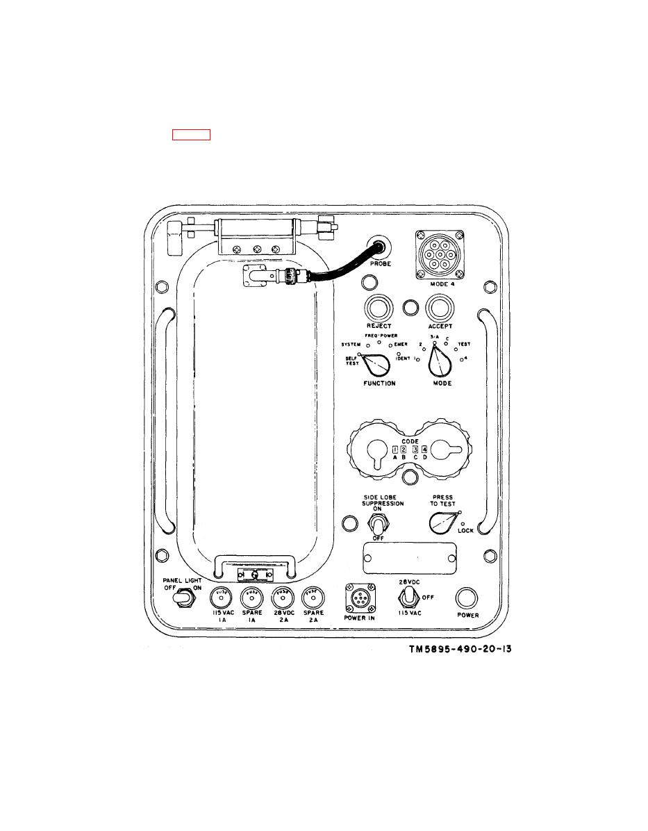
Figure 3-3. Test Set, Transponder AN/APM-1234(V)1, controls and indicators. |
|
||
| ||||||||||
|
|
 NAVSHIPS 0967-217-4010
TM 11-5895-490-20
latch. Swing the antenna up until a
the ANT. J5 connector on the RT-
vertical detent locking pin locks the
859/APX-72.
(2) Release the AN/APM-123A(V)
cover latches and remove the cover.
b. Test Setup for Nonradiation Operation,
Remove the CG-409G/U rf cable and
Direct Coupling. (fig. 3-3)
the CN-1088A/U fixed attenuator
from the cover.
(1) Place the AN/APM-123A(V) near
controls and indicators.
Change 1
|
|
Privacy Statement - Press Release - Copyright Information. - Contact Us |
