 |
|||
|
|
|||
|
Page Title:
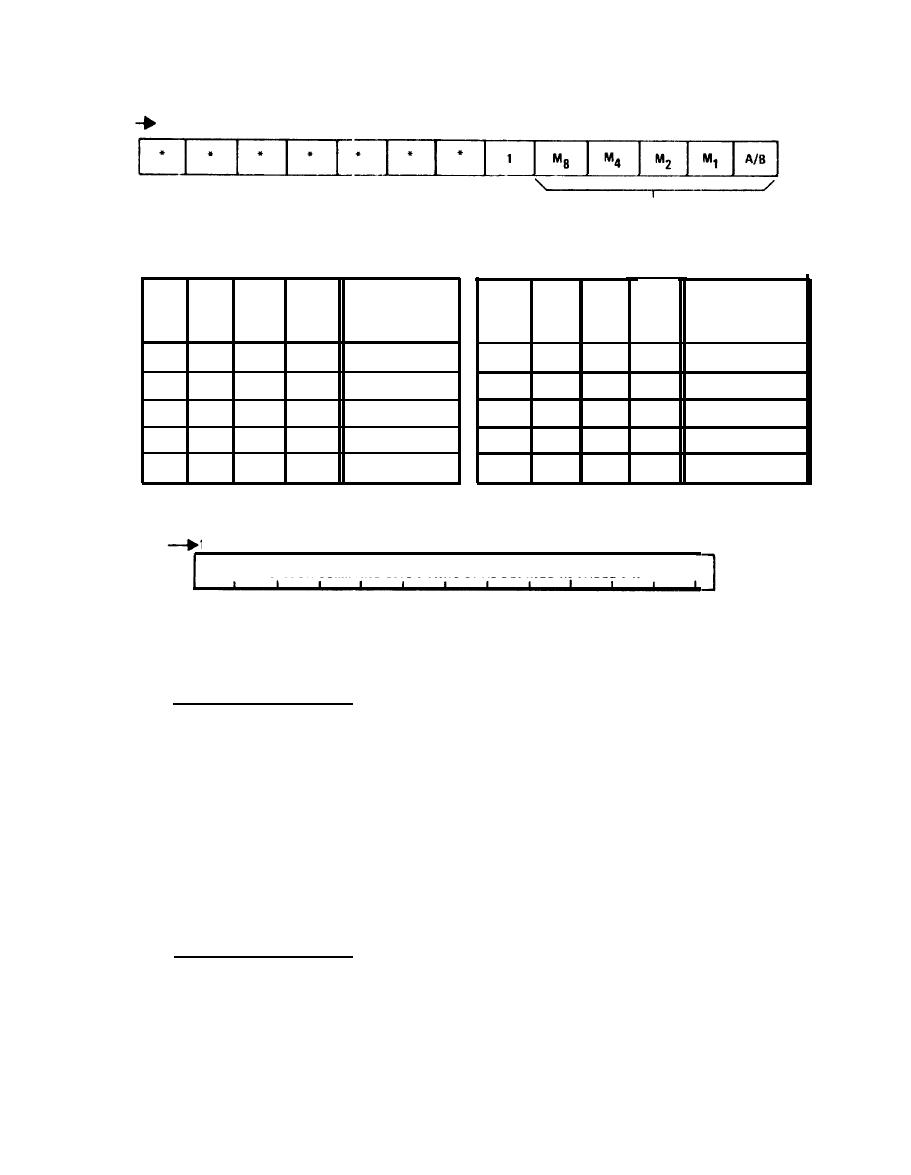
Figure 5-12. Receiver Command Input Format |
|
||
| ||||||||||
|
|
 TM 11-5865-215-13
5TH
9TH
8TH
6TH
10TH
11TH 12TH 13TH
7TH
2ND
3RD
4TH
SEQUENCE
1ST
SENT TO
RECEIVER
CONTROL
* = NOT USED
A/B =0 DENOTES INPUT DATA STORED IN FILE A
1 = UNIQUE BIT USED BY COMPUTER
A/B = 1 DENOTES INPUT DATA STORED IN FILE B
M1,M2,M4,M8 DENOTES LOCATION IN SELECTED
FILE WHERE THIS COMMAND DATA IS STORED
STORAGE
STORAGE
LOCATION OF
LOCATION OF
SELECTED FILE
SELECTED FILE
M8
M4
M2
M1
M2
M1
M8
M4
ZERO
1
0
0
0
o
o
0
1
FIVE
ONE
1
1
1
o
0
0
SlX
0
o
0
o
1
1
0
0
SEVEN
1
o
Two
0
0
o
1
0
EIGHT
1
1
THREE
0
NINE
0
0
FOUR
1
0
1
0
o
1
A
14TH THRU 64TH
SEQUENCE
SENT TO
I
I
I
I
I
I
I
1
I
I
I
RECEIVER
RECEIVER COMMAND BITS 1 THRU 51 AS DEFINED IN TABLE 1-1.
I
CONTROL
(CONTINUED)
EL3RJ015
Receiver Command Input Format
(1) Timing sequence T1. Format counter U1 provides a low CO
(carryout, pin 7 ) when the output cycle is completed. Write gate U5C,
enabled by the output of the set write latch responds to this high by
producing a high (1) DATA/WRITE ENABLE signal. The write latch, U14C,
was set during the previous output cycle. The DATA WRITE ENABLE sig-
nal enables the preset inputs to format counters U1 and U2. Also, the
signal is read by the microprocessor via the I/O bus (I/00) and input
port 7 (IB70).
The high CO output of the format counters (U1-7) also activates
write timer U8 via inverter U7C. This time will count. the 13-kHz
clock (from control CCA A7 to provide a 54-ms time interval for the
write cycle.
(2) Timing sequence T2. The microprocessor responds to the high
DATA WRITE ENABLE bit (read at input port 7) by generating an output
format command via output port 4 (0B40 and 0B41) . This command is
preset into format counter, by the high DATA WRITE ENABLE signal, for
the subsequent output cycle. The high DATA WRITE ENABLE signal, how-
ever, prevents format counter operation until the output cycle is
initiated.
5-30
|
|
Privacy Statement - Press Release - Copyright Information. - Contact Us |
|
|
Integrated Publishing, Inc. - A (SDVOSB) Service Disabled Veteran Owned Small Business
|

