 |
|||
|
|
|||
|
|
|||
| ||||||||||
|
|
 TM 11-5865-215-13
EL3RJ004
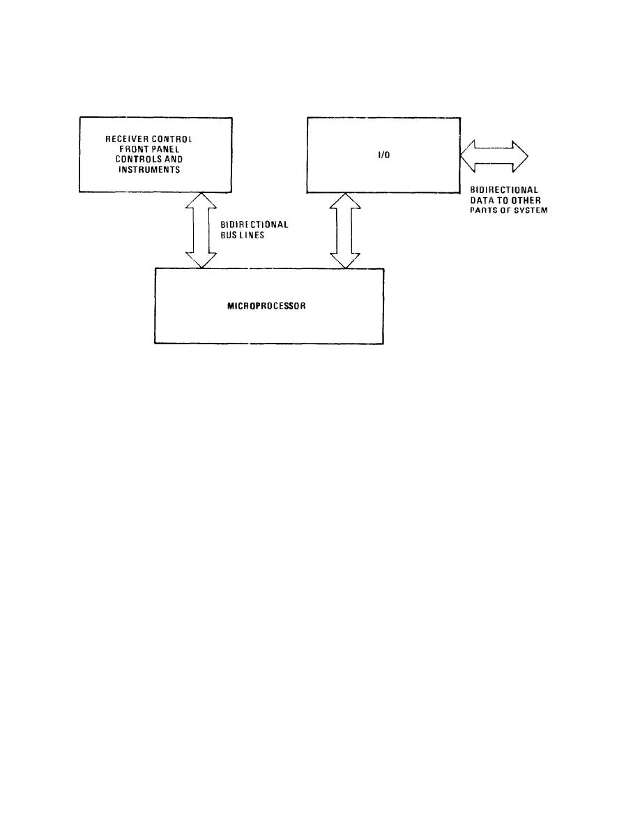
Receiver Control Simplified Block Diagram
Functional Description.
The elements of the receiver control communicate via a bidirec-
tional 1/0 bus and 14 unidirectional input and output ports (see
figure 5-2 and FO-5). The I/O bus, as well as the input and output
ports, provide a selectable 4-bit path by which the microprocessor
exchanges data with the following major groups of peripheral elements:
Front panel keyboard scan and lamp illumination circuits.
Front panel analog control conversion and interface circuits.
External unit interface circuits.
The peripheral elements are selected when the microprocessor gener-
ates a 4-bit output control signal (OCO, OC1, OC2, OC3). The OCO
thru OC3 code is accompanied by either an IN strobe, or an OUT strobe.
The IN strobe identifies a microprocessor read (input) operation. The
selected peripheral element responds by feeding data to the micropro-
cessor via the 1/0 bus, or to an assigned input port (depending on
the OCO thru OC3 code). An OUT strobe identifies a microprocessor
write (output) operation. During this operation the microprocessor
sends data, an address, or a command to the peripheral element via
the 1/0 bus or output port selected by the OCO thru OC3 bits.
|
|
Privacy Statement - Press Release - Copyright Information. - Contact Us |
|
|
Integrated Publishing, Inc. - A (SDVOSB) Service Disabled Veteran Owned Small Business
|

