 |
|||
|
|
|||
|
|
|||
| ||||||||||
|
|
 TM 11-5865-215-13
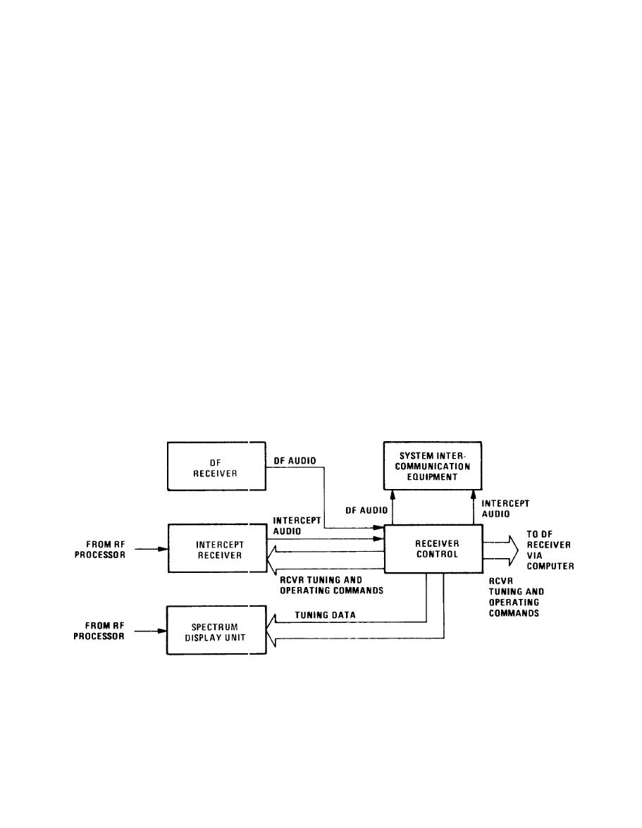
duplicated in the computer for the purpose of updating the receiver
control file in the event of a power loss. Tuning data generated by
the receiver control are also routed to Panoramic Indicator IP-1337/U
(SDU display) for tuning. A typical equipment arrangement is shown
in figure 1-2.
Description.
The receiver control is a solid-state, air-cooled modular unit in-
Front panel components include 39
tended for rack-mounted operation.
keys, a 6-digit frequency display, six control knobs, and one headset
Six internal
connector for control and monitoring of the receiver.
circuit card assemblies (CCAs) translate front panel keyboard selec-
tions and control knob positions into a serial receiver control word
(see table 1-1). The control word is transferred to the system re-
This function is controlled by a
ceivers and panoramic indicator.
microprocessor which first scans the status of the front panel con-
trols, then branches into the data conversion process in response to
any activated switch. Table 1-2 lists the equipment comprising an
operable receiver control..
EL3RJ002
Typical Receiver Control Application
1.3
|
|
Privacy Statement - Press Release - Copyright Information. - Contact Us |