 |
|||
|
|
|||
|
|
|||
| ||||||||||
|
|
 TM 32-5865-061-24&P
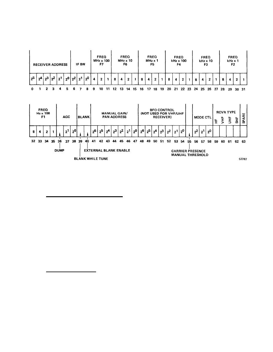
RC Bus Data Format
3 - 2 . 3 R e f e r e n c e a n d S t a t u s S i g n a l s . T h e b u f f e r a m p l i f i e r , C C A A5, produces four
5 M H z r e f e r e n c e c l o c k s i g n a l s f o r s y s t e m u s e . T h e s e signals are derived from the
T h r e e unbalanced 50 ohm and one differential sine wave
5 MHz REF input to A5.
o u t p u t a r e p r o v i d e d . A 5 also provides temperature and enclosure fault status
s i g n a l s . T e m p e r a t u r e status is obtained from a temperature sensor located inside
t h e u n i t . W h e n the measured temperature exceeds 155 degrees F (68 degrees C), the
sensor contacts open to produce the TEMP IND signal. Power supply monitor, A6,
produces two fault status signals when one or more of the supply voltages fail.
O n e signal is provided as an output, the other is fed to A5. The ENCLOSURE FAULT
status signal is produced by monitoring the 5 MHz REF, TEMP IND, and PWR SPLY STAT
signal inputs. A fault condition results in the output of differential signal
ENCLOSURE FAULT. L o c a l i n d i c a t i o n o f a f a u l t c o n d i t i o n i s a l s o p r o v i d e d ( f r o n t
panel lamps).
3 - 2 . 4 P o w e r D i s t r i b u t i o n . T h e ac power to the Receiver Set is applied to the
p o w e r supply modules and a cooling fan through EMI filter A7, the POWER ON/OFF
s w i t c h S I , a n d c i r c u i t b r e a k e r s C B 1 - C B 5 . T h e power supply modules are encap-
sulated and have built in regulation and over current protection circuits. The
o u t p u t s of DC power supplies are fed to power supply monitor A6. A6 monitors t h e
power supply voltages and provides: an external indication when all six are
p r e s e n t (lamps in POWER ON/OFF switch S1), fault status signals, overvoltage
protection.
|
|
Privacy Statement - Press Release - Copyright Information. - Contact Us |
