 |
|||
|
|
|||
|
Page Title:
Table 5-1. Troubleshooting Procedures - continued |
|
||
| ||||||||||
|
|
 TM 5-6350-264-14&P-12
NAVELEX EE 181-AA-OMI-120/E121 C-7359-60-1
TO 31S9-2FSS9-1-12
Table 5-1. Troubleshooting Procedures - Continued
Corrective action
Probable cause
Trouble
c. If this indication is not correct, re-
h. (cont)
1. (cont)
place Data Receiver.
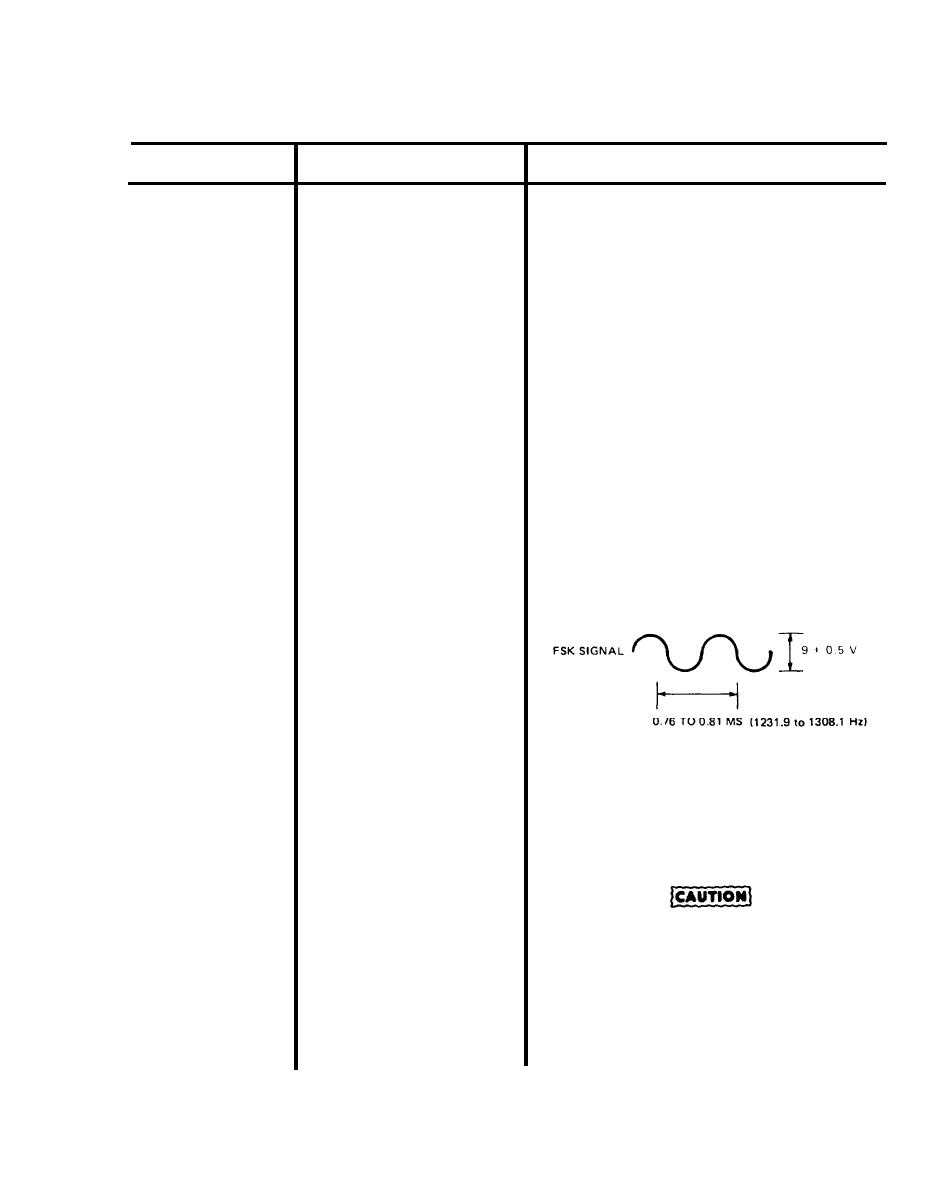
d. If clock signal is good, use oscillo-
scope to check FSK signal on
Data Receiver PC board A4. Set
oscilloscope as follows:
@2v
volts/division
@0.1ms
time/division
input
@ac
At the receiver connect scope
probe to A4-TP6 (blue) and scope
ground to A4-TP3 (orange). At
the transmitter, ground A1-TP5
(green) by connecting a jumper
from A1-TP5 to transmitter
chassis. The scope should display
FSK signal as a sine wave of 9
0.5 vac, and 0.81 to 0.76 ms
(1231.9 to 1308.1 Hz).
e. Set multimeter to dc volts and con-
nect positive lead to A4-TP7
(violet), and negative meter lead
to A4-TP3 (orange). Meter should
indicate 9 2 vdc.
Do NOT short A1-E14 to chassis/
ground or equipment will be
damaged.
5-19
|
|
Privacy Statement - Press Release - Copyright Information. - Contact Us |
