 |
|||
|
|
|||
|
Page Title:
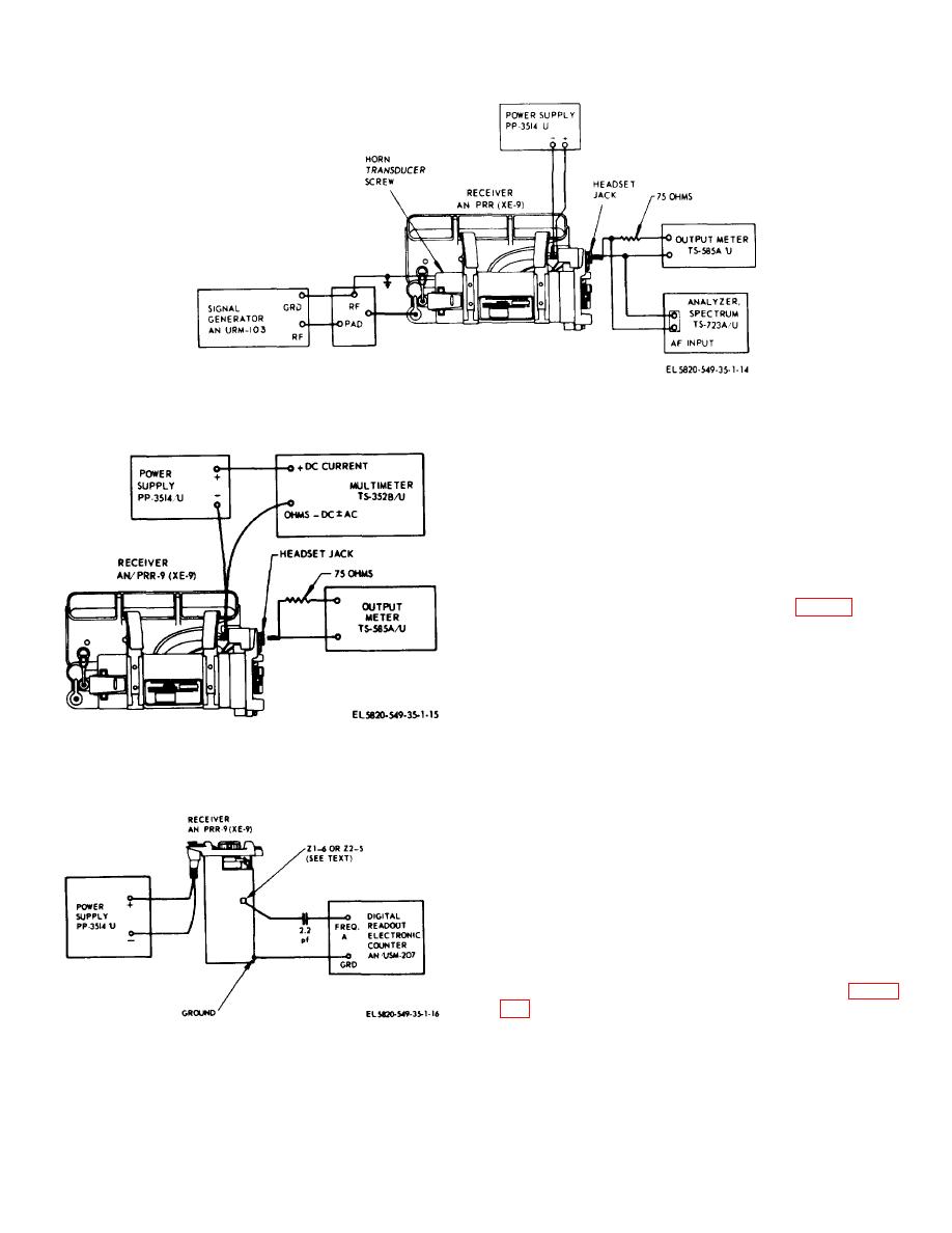
Figure 4-5. AN/PRR-9(XE-9) audio distortion test. |
|
||
| ||||||||||
|
|
 TM 11-5820-549-50-1
Figure 4-5. AN/PRR-9(XE-9) audio distortion test.
b. Set the PP-3514/U for 3.2 +0.1 volts input to the
receiver.
c. Set the AN/URM-103 for receiver channel
frequency. Read frequency on AN/USM-207.
d. Adjust receiver volume control for squelch "off"
operation.
e. Adjust output of AN/URM-103 for an indication
on the ME-30A/U of 4.8 millivolts at TP2 (fig. 2-2).
f. increase the output signal level of the AN/ URM-
103 by 6 db.
g. Tune the AN/URM-103 on each side of the
channel frequency until the ME-30A/U again reads 4.8
mv. Note and record the frequencies, as indicated on
the AN/USM-207, at which the ME-30A/U reads 4.8 mv.
h. The spread between the two frequencies
recorded in step g shall be 40 kHz + 10 kHz.
Figure 4-6. AN/PRR-9(XE-9) dc power consumption
test.
i. Increase the output signal level of the AN/ URM-
103 by an additional 54 db.
j. Repeat step g.
k. The spread between the two frequencies
recorded in step j shall be no more than 72.0 kHz.
4-14. AN/PRR-9(XE-9) Discriminator Characteristics
Test
For this test the receiver electronic unit assembly must
be removed from the receiver case.
b. Set the PP-3514/U for 3.2 +0.1 volts input to the
receiver.
Figure 4-7. AN/PRR-9(XE-P) oscillator tests.
c. Set the AN/GRM-50 for 455 kHz as indicated on
the AN/USM-207.
4-5
|
|
Privacy Statement - Press Release - Copyright Information. - Contact Us |
