 |
|||
|
|
|||
|
Page Title:
Table 5-1. Troubleshooting Procedures - continued |
|
||
| ||||||||||
|
|
 TM 5-6350-264-14&P-12
NAVELEX EE 181-AA-OMI-120/E121 C-7359-60-1
TO 31S9-2FSS9-1-12
Table 5-1. Troubleshooting Procedures - Continued
Corrective action
Probable cause
Trouble
f. At the Data Transmitter, disconnect
h. (cont)
1. (cont)
jumper from A1-TP5 to chassis.
Connect jumper from A1-TP5 to
A1-E14. Change oscilloscope set-
tings as follows:
@1.v
volts/division
time/division
@0.5ms
@ac
input
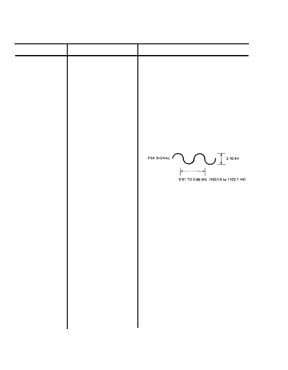
At Data Receiver, oscilloscope should
be connected to A4-TP6 and TP3.
The oscilloscope should display FSK
signal as a sine wave of 2 0.4 v and
0.91 to 0.96 ms (1037.9 to 1102.1 Hz).
g. The multimeter, still connected to
A4-TP7 and TP3, should indicate
less than 1 vdc.
h. If any of these scope or meter indica-
tions of the FSK signal are incorrect,
replace Data Receiver.
i. Remove all test leads and test equip-
ment from Data Transmitter and
Data Receiver.
(1) To remove Data Receiver, turn
off switch S1 on power supply.
Remove screws that secure
Status Monitor Module to rack
and remove module through
front of rack. Remove tape
or string and remove Data
Receiver from bottom of
module. Remove code plug
from its socket on PC board
A1.
5-20
|
|
Privacy Statement - Press Release - Copyright Information. - Contact Us |
