 |
|||
|
|
|||
|
Page Title:
Table 5-1. Troubleshooting Procedures - continued |
|
||
| ||||||||||
|
|
 TM 5-6350-264-14&P-12
NAVELEX EE 181-AA-OMI-120/E121 C-7359-60-1
TO 31S9-2FSS9-1-12
Table 5-1. Troubleshooting Procedures - Continued
Corrective action
Probable cause
Trouble
Remove screws that secure cover.
h. (cont)
1. (cont)
Remove captive screws and re-
move Receiver cover. Plug Data
Receiver into status monitor mod-
ule and temporarily secure with
string and tape. Ensure that test
points on bottom edge of PC
boards are not covered. Replace
status monitor module in swing-
out rack and secure with screws.
Turn on switch S1 on power
supply. Wait one or two minutes
for system to stabilize; then push
RESYNC button in CU.
a. At rear of Data Receiver, check
line fault indicator (LFI) LED.
If LFI is lighted, push RESET
LFI switch next to it. If LFI
does not go out, press RESYNC
switch in CU.
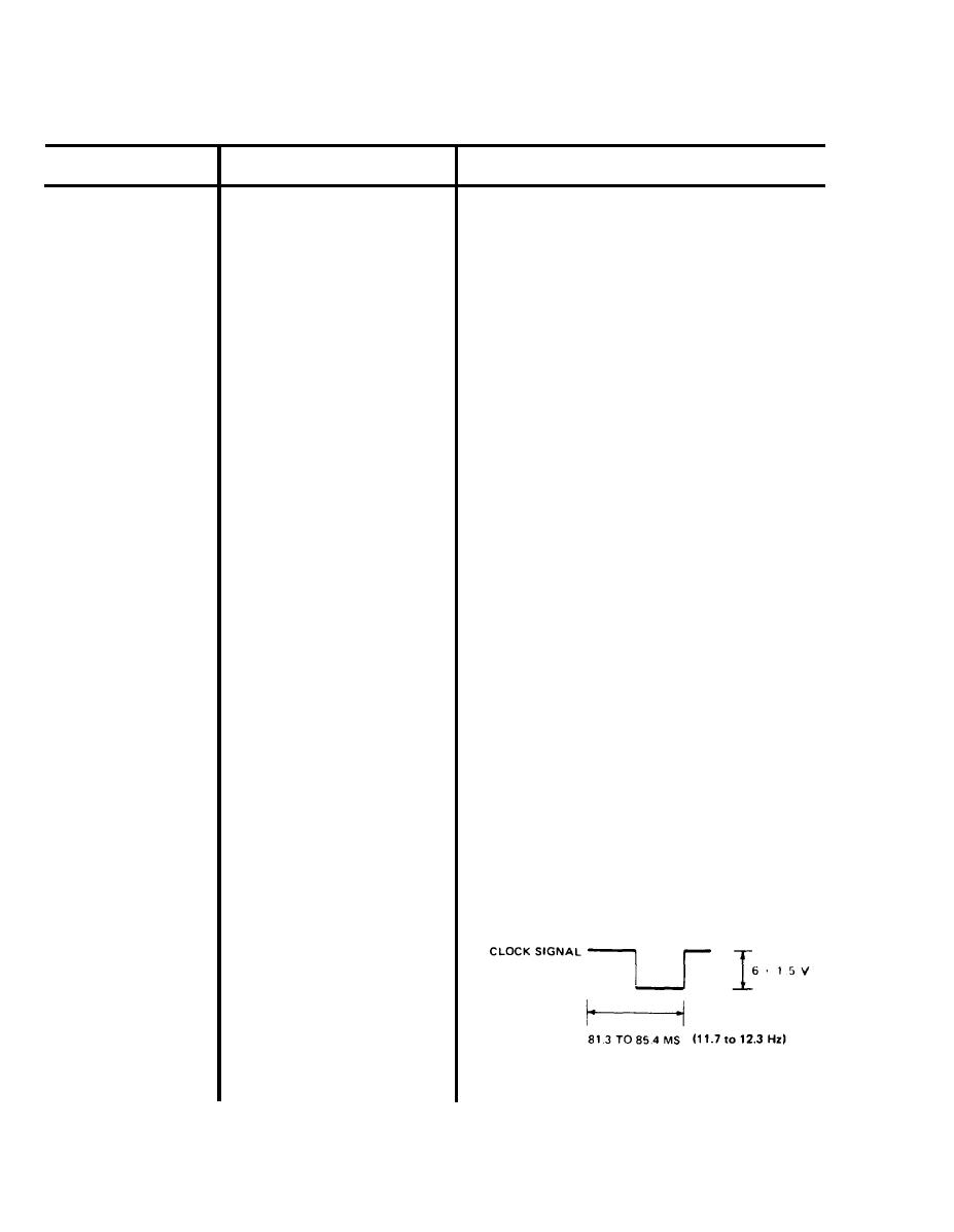
b. If LFI does not go out, use oscil-
loscope to check clock signal on
PC board A2. Set oscilloscope
as follows:
volts/division
@2v
time/division
@10ms
input
@dc
Connect scope probe to A2-TP6
(blue) and scope ground to
A4-TP3 (orange). The scope
should display clock signal as a
squarewave of 6.8 0.4 vdc, and
85.4 to 81.3 ms (11.7 to 12.3 Hz).
5-18
|
|
Privacy Statement - Press Release - Copyright Information. - Contact Us |
