 |
|||
|
|
|||
|
Page Title:
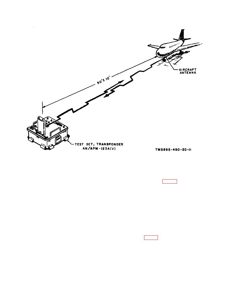
Figure 3-1. Test setup for radiation operation. |
|
||
| ||||||||||
|
|
 NAVSHIPS 0967-217-4010
TM 11-5895-490-20
.
Test setup for radiation operation.
(5) To position the AN/APM-123A(V)
Warning: Pressure must be released before
for horizontally polarized aircraft
the cover is removed from the AN/APM-
transponder antennas, grasp the an-
123A(V) beeause the cover may spring up
tenna handle (fig. 3-2) and gently
forcibly and cause serious injury.
pull up the antenna to disengage it
(2) Place the AN/APM-123A(V) 50
from a snap latch. Swing the antenna
10 feet from the AT-84A/APX
up until a vertical detent locking pin
(or equivalent) avoiding obstruc-
locks the antenna. Pull the antenna
tions in the path between the AN/
up at the right-hand corner to un-
APM-123A(V) and the aircraft an-
lock it from the vertical detent lock-
tenna.
ing pin. Lift the antenna up until a
(3) Remove the AN/APM-123A(V)
horizontal detent pin locks the an-
cover by releasing its latches.
tenna,
(4) Position the AN/APM-123A(V) so
(6) To position the antenna for vertical
that the front panel faces the sky
polarization, grasp the antenna han-
and the arrow on the adjustable an-
tenna is directed toward the aircraft
dle (fig. 3-2) and gently pull up the
transponder antenna.
antenna to disengage it from a snap
|
|
Privacy Statement - Press Release - Copyright Information. - Contact Us |
