 |
|||
|
|
|||
|
|
|||
| ||||||||||
|
|
 TM 11-5820-549-50-1
Kz external modulation from the TS-421A/U. The
f. Adjust the AN/URM-48 output successively to
AN/URM-103 output should be zero at this point.
10,000, 1,000, 500, 100, 10, and 1.0 microvolt levels,
e. Set the receiver volume control for maximum,
noting the change from the 3.5 milliwatt (mw) reference
level as indicated on the TS-585A/U at each of these
squelched operation. Remove plug from headset jack
steps. Output level shall not vary more than 1.75 mw
and listen to horn transducer to be sure receiver is
at any of the settings of the AN/URM-103.
squelched. Then replace plug in headset jack.
f. Increase the AN/URM-103 output until current
4-9.
AN/PRR-9(XE-9) Audio Frequency Response
on TS-352B/U increases approximately 10 to 12
Test
milliamperes.
g. Note and record indication of AN/URM103 RF
ATTENUATOR MICROVOLTS dial.
b. Set the PP-3514/U for 3.2 0.1 volts input to the
h. AN/URM-103 output shall not exceed 0.4
receiver.
microvolts.
c. Set the TS-585A/U for 150 ohms.
4-8. AN/PRR-9(XE-9) Limiting Test
d. Set the AN/URM-48 to the receiver channel
With the exception of the TS-723A/U, this test uses the
frequency at 5,000 microvolts output level.
same test setup as figure 4-2. The receiver is operated
e. Set the TS-421A/U for 1,000 cps and adjust
on any normal channel frequency.
output for an indication on the AN/URM48 of 8.0 kc
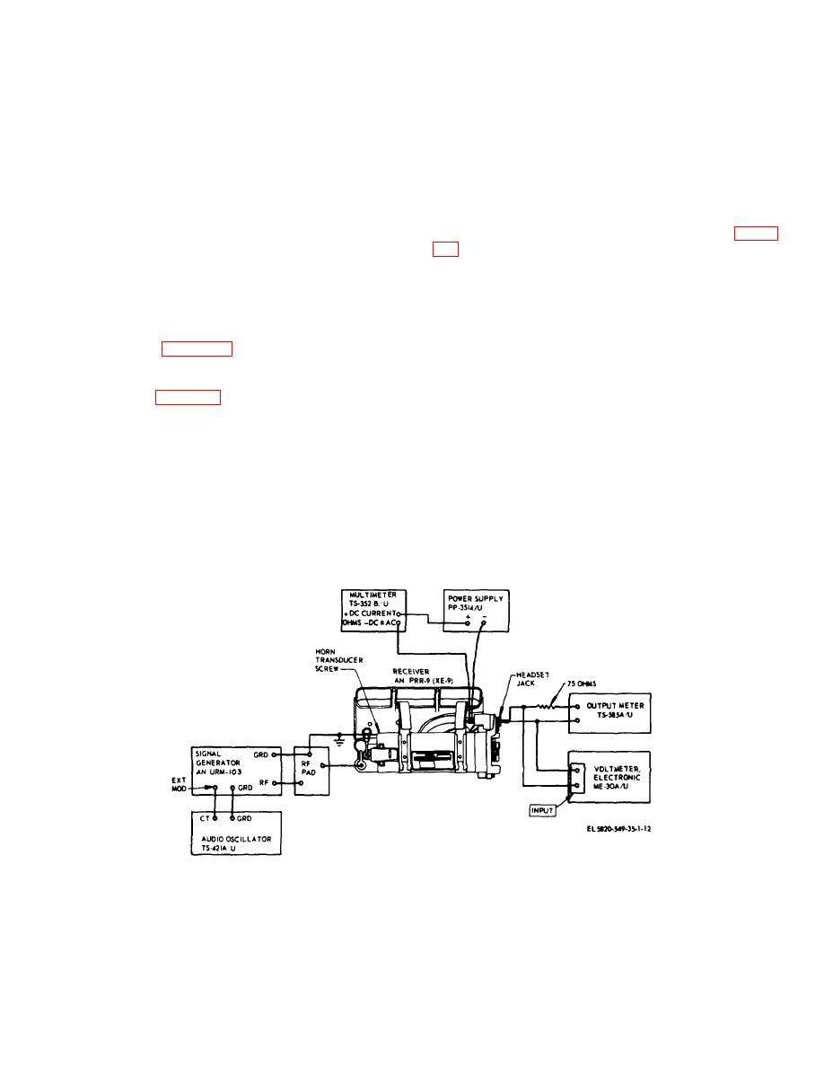
a. Connect the test equipment, with the exception
deviation.
cited, as shown in figure 4-2.
f. Set the receiver volume control to squelch "off"
b. Set the PP-3514/U for 3.2 0.1 volts input to the
and adjust for a 3.5 milliwatt indication on the TS-
receiver.
585A/U.
c. Set the TS-585A/U for 150 ohms.
g. Note the db indication on the ME-30A/U. This is
d. Set the AN/URM-103 to receiver channel
the reference level for subsequent measurements.
frequency and 8.0 kc deviation at 1,000 cps. Set the
h. Change the TS-421A/U modulating frequence
generator output at 100,000 microvolts.
successively, to the frequencies indicated below.
e. Adjust the receiver volume control for 8.5
Output changes as indicated on the ME30A/U shall be
milliwatts output as indicated on the TS-585A/U. This
within the range shown in the "Response" column below.
output is the reference level.
Figure 4-3. AN/PRR-9 (XE-9) squelch sensitivity test.
4-3
|
|
Privacy Statement - Press Release - Copyright Information. - Contact Us |
